
Useful logging script from RackSpace:
https://github.com/rackerlabs/recap.git
See the readme file for instructions.
Useful logging script from RackSpace:
https://github.com/rackerlabs/recap.git
See the readme file for instructions.
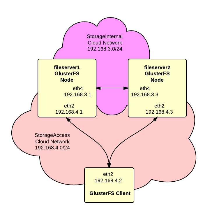 We want to build a high-availability storage cluster based on GlusterFS using RackSpace Cloud Servers on Ubuntu. Additionally we want to use RackSpace Cloud Networks to provide private networks for replication and cluster access.
There’s a great doc by Falko Timme on Howto Forge titled:
We’re going to follow this doc with a few modifications for Cloud Networks and using a newer version of Gluster.
As shown in the diagram, we’ll have two Cloud Networks, one for replication between the servers and one for access by clients to the storage.
1. Create servers and networks – Login to your RackSpace Cloud account and create two server following these guidelines:
Here are the addresses assigned to the servers that we created but yours my be different:
|
1 2 3 4 |
fileserver1 ServiceNet 10.10.10.1 (eth1) StorageAccess 192.168.4.1 (eth2) StorageInternal 192.168.3.1 (eth4) |
and:
|
1 2 3 4 |
fileserver2 ServiceNet 10.10.10.2 (eth1) StorageAccess 192.168.4.3 (eth2) StorageInternal 192.168.3.3 (eth4) |
2. Open SSH shell to servers – Open an SSH shell to each of the servers. Unless noted otherwise the following steps should be repeated on both servers.
3. Upgrade packages – Update repository listings and then upgrade all packages to latest versions:
|
1 2 |
apt-get update apt-get upgrade |
4. Setup /etc/hosts – Add hostnames on the “StorageInternal” network for each server.
|
1 2 |
192.168.3.1 fileserver1-si 192.168.3.3 fileserver2-si |
5. Install glusterfs PPA repository – The default apt repositories for Ubuntu only offer version 3.2.7 of GlusterFS. We wanted a newer version so we’ll be modifying the install process to use the PPA distribution. Execute the following commands
|
1 2 3 4 |
apt-get install python-software-properties apt-get install software-properties-common add-apt-repository ppa:semiosis/ubuntu-glusterfs-3.3 apt-get update |
6. Install glusterfs server – Use this command to install:
|
1 |
apt-get install glusterfs-server |
7. Confirm gluster version – Make sure you have the correct version:
|
1 2 |
root@fileserver1:~# glusterfsd --version glusterfs 3.3.2 built on Jul 21 2013 16:38:01 |
If you get an older version then you probably forgot to run “apt-get update”. Just remove the older package, update and reinstall:
|
1 2 3 |
apt-get remove glusterfs-server apt-get update apt-get install glusterfs-server |
8. Firewall configuration – Next we need to get a basic firewall configured to protect the servers. Ubuntu includes UFW (Uncomplicated Firewall) so we’ll go with that:
|
1 2 3 4 5 6 7 8 9 10 11 |
# allow incoming ssh ufw allow 22 # allow all connections on "StorageInternal" network ufw allow in on eth4 # allow all connections on "StorageAccess" network ufw allow in on eth2 # turn on the firewall ufw enable |
9. Add nodes to cluster – On fileserver1, run this command to register fileserver2 to the trusted storage pool:
|
1 |
gluster peer probe fileserver2-si |
The results should look like this:
|
1 2 |
root@fileserver1:~# gluster peer probe fileserver2-si Probe successful |
10. Check cluster status – On each node run “gluster peer status” and confirm the peer addresses. Here’s fileserver1:
|
1 2 3 4 5 6 |
root@fileserver1:~# gluster peer status Number of Peers: 1 Hostname: fileserver2-si Uuid: 128a6848-9681-4ef4-ac34-283875755ccd State: Peer in Cluster (Connected) |
and here’s fileserver2:
|
1 2 3 4 5 6 |
root@fileserver2:~# gluster peer status Number of Peers: 1 Hostname: 192.168.3.1 Uuid: 79a0c485-7d7f-4f90-9956-61de48074f84 State: Peer in Cluster (Connected) |
11. Create volume – Next we need to create the actual GlusterFS volume:
|
1 2 |
gluster volume create datavol replica 2 \ transport tcp fileserver1-si:/data fileserver2-si:/data |
You should get back a response like:
|
1 2 |
Creation of volume datavol has been successful. Please start the volume to access data. |
12. Start the volume – Now start the volume to make it available to clients with:
|
1 |
gluster volume start datavol |
You should get a response like:
|
1 |
Starting volume datavol has been successful |
The howto by Falko Timme mentioned at the start of this article gives some useful advice and tips on how to troubleshoot if the volume fails to create or start.
13. Verify volume status – Check the status of the volume with:
|
1 |
gluster volume info |
You should get a response similar to:
|
1 2 3 4 5 6 7 8 9 |
Volume Name: datavol Type: Replicate Volume ID: 3107a27c-2f70-43da-8ce4-ad270641e314 Status: Started Number of Bricks: 1 x 2 = 2 Transport-type: tcp Bricks: Brick1: fileserver1-si:/data Brick2: fileserver2-si:/data |
14. Allow client access – We want to allow all clients on the “StorageAccess” network access to the cluster:
|
1 |
gluster volume set datavol auth.allow 192.168.4.* |
Now show volume info again:
|
1 |
gluster volume info |
And you should get:
|
1 2 3 4 5 6 7 8 9 10 11 |
Volume Name: datavol Type: Replicate Volume ID: 3107a27c-2f70-43da-8ce4-ad270641e314 Status: Started Number of Bricks: 1 x 2 = 2 Transport-type: tcp Bricks: Brick1: fileserver1-si:/data Brick2: fileserver2-si:/data Options Reconfigured: auth.allow: 192.168.4.* |
Setup on the server is complete. Now it’s time to add clients.
1. Install glusterfs PPA repository – Execute the following commands
|
1 2 3 4 |
apt-get install python-software-properties apt-get install software-properties-common add-apt-repository ppa:semiosis/ubuntu-glusterfs-3.3 apt-get update |
2. Install glusterfs client – Execute the following command:
|
1 |
apt-get install glusterfs-client |
3. Confirm version – Verify that you have the correct version installed:
root@db1:~# glusterfs –version
glusterfs 3.3.2 built on Jul 21 2013 16:38:01
4. Create mount point – Create a directory that will be the mount point for the gluster partition:
|
1 |
mkdir /data |
5. Setup /etc/hosts – Add the following entries to /etc/hosts:
|
1 2 |
192.168.4.1 fileserver1-sa fileserver1-si 192.168.4.3 fileserver2-sa fileserver2-si |
Notice that we’re mapping both the StorageInternal and StorageAccess network names to the same IP addreses on the StorageAccess network.
6. Mount volume – Execute the command to mount the gluster volume:
|
1 |
mount -t glusterfs fileserver1-sa:/datavol /data |
7. Edit /etc/fstab – Add this line to /etc/fstab to make the mount start automatically on boot:
|
1 |
fileserver1-sa:/datavol /data glusterfs defaults 0 0 |
And that completes the client setup procedure. You now have a working GlusterFS storage cluster and a connected client.
Comments and suggestions are welcomed.
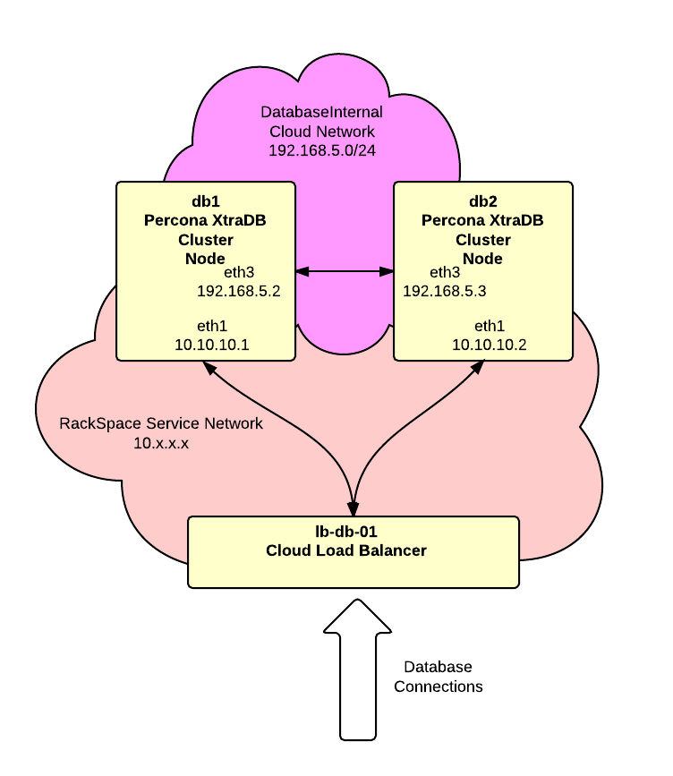 In this article we’re going to build a Percona XtraDB Cluster using a pair of RackSpace Cloud Servers. Percona XtraDB Cluster is a MySQL compatible replacement supporting multi-master replication. For this project we’ll use the latest Ubuntu release and we’re going to use RackSpace Cloud Networks to setup an isolated segment for the replication between the cluster nodes. We’ll do two nodes in the cluster but you can add additional nodes as desired. Finally we’ll use a RackSpace Cloud Load Balancer to distribute traffic between the nodes.
To get started, create the cloud servers from the RackSpace control panel using the following guidelines:
For this article we’ll assume that the “DatabaseInternal” cloud network is:
|
1 |
192.168.3.0/24 |
and our servers are:
|
1 2 3 4 |
db1.acme.com public: 1.1.1.1 private: 10.10.10.1 DatabaseInternal: 192.168.5.2 |
and:
|
1 2 3 4 |
db2.acme.com public: 1.1.1.2 private: 10.10.10.2 DatabaseInternal: 192.168.5.3 |
Here are the basic instructions from Percona that we’ll be following:
http://www.percona.com/doc/percona-xtradb-cluster/installation.html
To get started open SSH terminal sessions to each server and complete the following steps on each server unless noted otherwise:
1. Disable apparmor – the Percona docs state that the cluster will not work with apparmor and it must be disabled. Here are the steps:
|
1 2 3 4 |
/etc/init.d/apparmor stop /etc/init.d/apparmor teardown update-rc.d -f apparmor remove apt-get remove apparmor apparmor-utils |
Now reboot the server to get a clean system without apparmor running.
2. Configure firewall – Next we need to get a basic firewall configured to protect the servers. Ubuntu includes UFW (Uncomplicated Firewall) so we’ll go with that:
|
1 2 3 4 5 6 7 8 |
# allow incoming ssh ufw allow 22 # allow all connections on "DatabaseInternal" network ufw allow in on eth3 # turn on the firewall ufw enable |
If you’re not familier with UFW then here’s a good starting point:
https://help.ubuntu.com/community/UFW
3. /etc/hosts – Let’s add some entries to the /etc/hosts file:
|
1 2 |
192.168.5.2 db1-dbint 192.168.5.3 db2-dbint |
4. Add Percona apt Repository – Just follow the instructions here:
http://www.percona.com/doc/percona-xtradb-cluster/installation/apt_repo.html
The exact lines for sources.list are:
|
1 2 |
deb http://repo.percona.com/apt raring main deb-src http://repo.percona.com/apt raring main |
Don’t forget to run:
|
1 |
apt-get update |
5. Install packages – Run the following command to install the cluster packages:
|
1 2 |
apt-get install percona-xtradb-cluster-server-5.5 \ percona-xtradb-cluster-client-5.5 |
You’ll be prompted by the installer to enter a root password for MySQL.
6. /etc/my.cnf – Setup configuration files on each server. The Percona distribution does not include a my.cnf file to you need to role your own. The minimal configuration would be something like this:
|
1 2 3 4 5 6 7 8 9 10 |
[mysqld] wsrep_node_address=192.168.5.3 wsrep_provider=/usr/lib/libgalera_smm.so wsrep_cluster_address=gcomm://db01-dbint wsrep_slave_threads=8 wsrep_sst_method=rsync binlog_format=ROW default_storage_engine=InnoDB innodb_locks_unsafe_for_binlog=1 innodb_autoinc_lock_mode=2 |
Most of this is straight from the Percona documentation. Key lines are:
|
1 |
wsrep_node_address=192.168.5.3 |
This tells Percona what address to advertise to other nodes in the cluster. We need this set to the server “DatabaseInternal” interface. Without this setting SST will fail when it uses the wrong interface and is blocked by the firewall.
|
1 |
wsrep_cluster_address=gcomm://db01-dbint |
This line identifies at least one other member in the cluster. Notice that we’re using the names we set in the /etc/hosts file.
The above example for my.cnf is very minimal. It does not address any database memory or performance tuning issues so you’ll likely want to expand upon the example.
7. /root/.my.cnf – Add a .my.cnf for MySQL root authentication as described here:
http://blogs.reliablepenguin.com/2012/10/09/create-my-cnf-file-for-mysql-authentication
This step is optional. The .my.cnf is convenient but should not be used in high security environments.
8. Bootstrap Cluster – The cluster needs to be bootstrapped on the first server when it’s started for the first time. This can be accomplished with:
|
1 |
/etc/init.d/mysql bootstrap-pxc |
The subject of bootstrapping is covered in more detail here:
http://www.percona.com/doc/percona-xtradb-cluster/manual/bootstrap.html
The first node startup will look something like this:
|
1 2 3 |
root@db1:~# /etc/init.d/mysql bootstrap-pxc * Bootstrapping MySQL (Percona XtraDB Cluster) database server mysqld [ OK ] * Checking for corrupt, not cleanly closed and upgrade needing tables. |
Now with the first node started, open a mysql command shell and view the wsrep_cluster_% status variables:
|
1 2 3 4 5 6 7 8 9 10 |
mysql> show status like "wsrep_cluster_%"; +--------------------------+--------------------------------------+ | Variable_name | Value | +--------------------------+--------------------------------------+ | wsrep_cluster_conf_id | 1 | | wsrep_cluster_size | 1 | | wsrep_cluster_state_uuid | 67d8795f-1339-11e3-94f1-9b7bbcee0e35 | | wsrep_cluster_status | Primary | +--------------------------+--------------------------------------+ 4 rows in set (0.01 sec) |
Notice that the wsrep_cluster_size is 1 and the wsrep_cluster_status is “Primary”. This is normal for the first node in a newly bootstrapped cluster.
Now we’ll start Percona normally on each additional server. So go to db2 and run:
|
1 |
/etc/init.d/mysql start |
This time the start should look something like this:
|
1 2 3 4 |
root@db2:~# /etc/init.d/mysql start * Starting MySQL (Percona XtraDB Cluster) database server mysqld * SST in progress, setting sleep higher mysqld [ OK ] * Checking for corrupt, not cleanly closed and upgrade needing tables. |
Startup for the second node adds the SST or “State Snapshot Transfer”. In this step the servers will use rsync and SSH keys to transfer a copy of the the database from the first server to the second server.
Back on the first server in our mysql command shell we can check the status again:
|
1 2 3 4 5 6 7 8 9 10 |
mysql> show status like "wsrep_cluster_%"; +--------------------------+--------------------------------------+ | Variable_name | Value | +--------------------------+--------------------------------------+ | wsrep_cluster_conf_id | 2 | | wsrep_cluster_size | 2 | | wsrep_cluster_state_uuid | 613f8f9a-133a-11e3-b4e0-9b8eeba56f39 | | wsrep_cluster_status | Primary | +--------------------------+--------------------------------------+ 4 rows in set (0.00 sec) |
Notice now according to the “wsrep_cluster_size” there are 2 nodes in the cluster.
At this point we have a functional cluster up and running.
If the second node fails to start then check the log file at:
/var/lib/mysql/db2.err
The most likely cause is a problem resolving or connecting to the db1-int server for SST.
9. Disable /etc/mysql/debian-start – The debian/ubuntu distribution of Percona includes a script at /etc/mysql/debian-start that checks and repairs tables on startup. We think this script is a bad idea in the cluster environment and should be disabled by running this command on each node:
|
1 |
touch /etc/mysql/NO-DEBIAN-START |
10. Add extra functions – There are a couple of Percona specific functions that can be added to support monitoring:
|
1 2 3 |
mysql -e "CREATE FUNCTION fnv1a_64 RETURNS INTEGER SONAME 'libfnv1a_udf.so'" mysql -e "CREATE FUNCTION fnv_64 RETURNS INTEGER SONAME 'libfnv_udf.so'" mysql -e "CREATE FUNCTION murmur_hash RETURNS INTEGER SONAME 'libmurmur_udf.so'" |
11. Add load balancer – The next step is to add the RackSpace Cloud Load Balancer. The load balancer will provide a single IP address for clients to connect to. It will then distribute these connections to the nodes in the cluster.
a. Login to your RackSpace Cloud Control Panel.
b. Go to Hosting section and the Load Balancers tab.
c. Click the “Create Load Balancer” button.
d. In the “Identification” section, enter a name for the load balancer like “lb-db-01” and select the Region. Use the same Region that the cluster nodes are located in.
e. In the “Configuration” section, select “On the Private RackSpace Network” for the “Virtual IP”. Set the “Protocol” to “MySQL” and the port to “3306”. Set the “Algorithm” to “Least Connections”.
f. In the “Add Nodes” section, click the “Add Cloud Servers” button and select each of the servers in the cluster.
g. Click the “Create Load Balancer” button to save the new load balancer.
It may take a couple of minutes for the load balancer to be created. When complete the IP address assigned to the load balancer will be visible. We’ll assume for this article that the address is:
|
1 |
10.10.10.10 |
Notice that this is a private, unroutable address on the RackSpace Service Network. This address is not accessible from the public Internet but it is visible to other cloud servers and devices in the same region on the RackSpace Service network. This is the address that your web or application servers will use to connect to the database.
12. Load balancer access controls – To minimize exposure of the database servers we need to add access controls on the load balancer that will limit the range of addresses that are allowed to connect. Generally you’ll only want connections from your web or application servers. In the RackSpace Cloud control panel, drill down to your load balance, find “Access Control” rules at the bottom and add a rule or rules to allow your client servers. Of course if you’re dynamically adding and removing servers then it might not be possible to use these access controls. Or you might need to use the load balancer API to dynamically change access controls.
13. Allow load balancer on firewalls – Next we need to adjust the firewall on each node to allow MySQL connections from the load balancer. The connections from the load balancer to the cluster nodes do not come from the load balancer address. Instead they can come from a range of addresses. The exact range depends on what region the load balancer was created in. At the time of writing this article the ranges were:
For the DFW region, use:
10.183.248.0/22
10.189.254.0/23For the IAD region, use:
10.189.254.0/23For the ORD region, use:
10.183.250.0/23
10.183.252.0/23
10.183.254.0/23For the LON region, use:
10.190.254.0/23For the SYD region, use:
10.189.254.0/23
This list may change over time. The latest ranges should be available here:
http://www.rackspace.com/knowledge_center/article/using-cloud-load-balancers-with-rackconnect
For this article we used the DFW region so the UFW rules would be:
|
1 2 |
ufw allow in on eth1 from 10.183.248.0/22 to any port 3306 ufw allow in on eth1 from 10.189.254.0/23 to any port 3306 |
14. Create database & users – Now we’re ready to create a database and user for our web application. For any of the cluster nodes, open a MySQL command shell, create the database and add a database user:
|
1 2 |
CREATE DATABASE mywebapp; GRANT ALL PRIVILEGES ON mywebapp.* TO 'mywebapp_user'@'%' IDENTIFIED BY 'some pass'; |
Now from your web application should be able to connect to the database cluster with the user that you just create. The database host should be the address of the load balancer.
15. Raise timeout – By default Cloud Load Balancers will timeout any idle connection after 30 seconds. This article shows how to raise the timeout:
https://community.rackspace.com/products/f/25/t/89
16. Add monitoring tools – You’ll probably want to add a few tools to monitor the database. Here’s what we normally install:
myq_gadets is a great set of monitoring utilites:
http://blogs.reliablepenguin.com/wp-admin/post.php?post=818&action=edit&message=6
mysqltuner helps adjust memory allocations based on actual performance:
|
1 |
wget mysqltuner.pl |
Percona Toolkit which can be downloaded from here:
http://www.percona.com/software/percona-toolkit
At this point you’re done! You have a working database cluster connected to your web application. Questions and comments are welcomed.
I was looking for a procedure to setup a new MySQL replication slave on Amazon AWS without having to do a MySQL dump of the master. Ended up using a couple of AWS features to make this an easy process. Let’s assume that we have a master server (master01) and a slave (slave01). We want to create a new slave (slave02). We’ll do this without taking the master offline and without doing a MySQL dump. This is especially important with large databases.
A couple of notes before we start:
Now here’s my procedure:
1. Login to AWS and go to EC2 -> Volumes. Find the volume holding the MySQL data. If you’ve not already done so we would recommend adding a Name tag to the volume so that you can easily see which server/function it is associated with. For example you might name it “slave01-mysql”. Right click on the volume and select “Create Snapshot”. A dialog will open where you can name the snapshot … something like “slave01-mysql-snap-1” would be appropriate. Depending on the size of the volume, this snapshot will take some time to complete.
One of the greatest features of EBS snapshots is their incremental nature. Here’s how it’s described by Amazon:
Amazon EBS snapshots are incremental backups, meaning that only the blocks on the device that have changed since your last snapshot will be saved. If you have a device with 100 GBs of data, but only 5 GBs of data has changed since your last snapshot, only the 5 additional GBs of snapshot data will be stored back to Amazon S3.
So the first snapshot we take of a volume has to copy the entire volume but additional snapshots only copy changed blocks. We’re going to use this is next step. At this point we have a snapshot of the server01 slave but it is inconsistent and we don’t have the point-in-time log coordinates that we need to initialize a new slave.
2. Login to slave01, stop replication and apply a read lock as follows:
|
1 |
mysql> slave stop; |
|
1 |
mysql> flush tables with read lock; |
Make sure that the “flush tables …” completes before proceeding. It may take a few seconds or more if there are locked tables that have to be released before the lock can be completed. At this point the slave server is not fully functional. You’ll want to proceed quickly through the next steps. Until the next step (3) is complete, do not close the terminal with the “flush tables …” as we need to keep the read lock active.
3. Open a second terminal session to slave01, record log coordinates and shutdown the mysql process as follows:
|
1 |
echo "show slave status\G" | mysql |
|
1 |
mysqladmin shutdown |
The slave status will look something like:
|
1 2 3 4 5 6 7 8 9 10 11 12 13 14 15 16 17 18 19 20 21 22 23 24 25 26 27 28 29 30 31 32 33 34 35 36 37 38 39 40 41 |
*************************** 1. row *************************** Slave_IO_State: Waiting for master to send event Master_Host: reportdb_master.prod.com Master_User: repl Master_Port: 3306 Connect_Retry: 60 <strong> Master_Log_File: bin-log.001998</strong> Read_Master_Log_Pos: 564896522 Relay_Log_File: mysqld-relay-bin.000007 Relay_Log_Pos: 564896666 Relay_Master_Log_File: bin-log.001998 Slave_IO_Running: Yes Slave_SQL_Running: Yes Replicate_Do_DB: Replicate_Ignore_DB: Replicate_Do_Table: Replicate_Ignore_Table: Replicate_Wild_Do_Table: Replicate_Wild_Ignore_Table: Last_Errno: 0 Last_Error: Skip_Counter: 0 <strong>Exec_Master_Log_Pos: 564896522</strong> Relay_Log_Space: 564896864 Until_Condition: None Until_Log_File: Until_Log_Pos: 0 Master_SSL_Allowed: No Master_SSL_CA_File: Master_SSL_CA_Path: Master_SSL_Cert: Master_SSL_Cipher: Master_SSL_Key: Seconds_Behind_Master: 0 Master_SSL_Verify_Server_Cert: No Last_IO_Errno: 0 Last_IO_Error: Last_SQL_Errno: 0 Last_SQL_Error: Replicate_Ignore_Server_Ids: Master_Server_Id: 501 |
The columns that we need to record are:
Exec_Master_Log_Pos
Master_Log_File
Take note of these values for later use.
The slave01 database is now stopped and we have the log coordinates from right before the shutdown.
4. Next in AWS, start a new snapshot of the slave01-mysql volume. Name it slave01-mysql-snap-2 or something similar. This snapshot will run much faster since it is only copying blocks that changed since the first snapshot.
5. When the second snapshot is complete, start the mysql process on the slave01 server. Check replication and confirm that it comes back in sync with the master. The slave01 is now back to a functional status.
6. In AWS, right click on the slave01-mysql-snap-2 snapshot and select “Create volume from snapshot”. Name the new volume something like slave02-mysql.
Another great feature of EBS snapshots is “lazy loading” as described here:
New volumes created from existing Amazon S3 snapshots load lazily in the background. This means that once a volume is created from a snapshot, there is no need to wait for all of the data to transfer from Amazon S3 to your Amazon EBS volume before your attached instance can start accessing the volume and all of its data. If your instance accesses a piece of data which hasn’t yet been loaded, the volume will immediately download the requested data from Amazon S3, and then will continue loading the rest of the volume’s data in the background.
This means that we can proceed with the new slave setup without waiting for the new volume to be loaded … instead it will load as needed.
7. In AWS, right click on the newly created volume and attach it to the new slave02 instance.
8. Login to the slave02 instance, confirm that mysql is stopped and mount the new volume.
9. Edit /etc/my.conf and add “skip-slave-start” to the “[mysqld]” section.
10. In the mysql data directory (/var/lib/mysql by default), remove the following files:
11. Start mysql server
12. Set replication config:
|
1 2 3 4 5 |
mysql> change master to master_host='YOUR_MASTER_HOST', master_user='YOUR_REPLICATION_USER', master_password='YOUR_REPLICATION_PASS', master_log_file='bin-log.001998', master_log_pos=564896522; |
13. Now start replication:
|
1 |
mysql> slave start; |
It may take a few minutes or more for replication on the new slave to catch up with the master. This is due to the “lazy load” on the volume created from the snapshot and the need to process the logs from the master.
Once the new slave catches up with the master then the task is complete and you have a new slave. This procedure can work with very large databases. There is no downtime on the master for this process. The existing slave is down for only a short period.
We’re going to build a highly secure hosting environment on RackSpace Cloud using Cloud Networks and the new Brocade Vyatta vRouter image. The diagrams shows the target configuration:
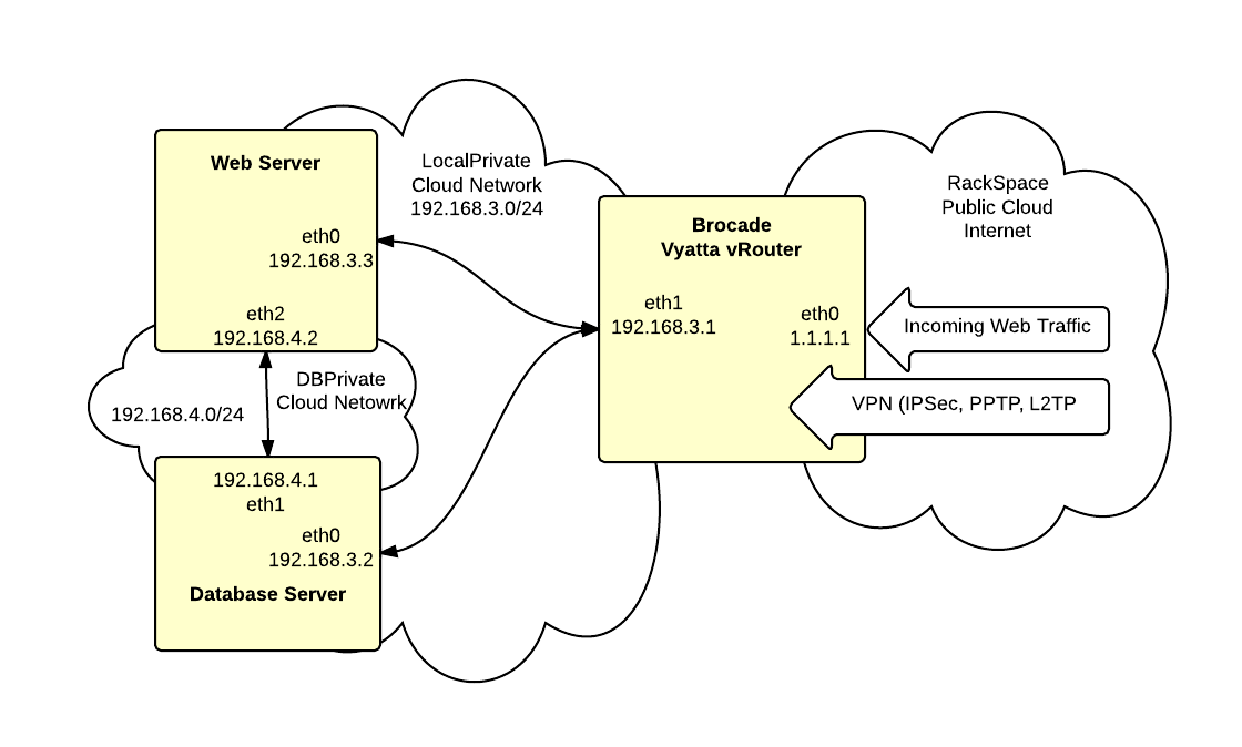
There are 4 networks:
Public – this is the RackSpace Public Cloud/Internet network. The vRouter connects via eth0 to this network with public address of 1.1.1.1
LocalPrivate – this is a private Cloud Network that connects the vRouter and the servers. This network uses the private 192.168.3.0/24 subnet.
DBPrivate – this is a private Cloud Network that connects the web and database servers. This network uses the private 192.168.4.0/24 subnet.
Service – this is RackSpaces multi-tenent management network. This network is not being used and is not shown in the diagram.
On these networks are three servers:
Brocade Vyatta vRouter – this device provides a router, firewall and VPN termination point
Web Server – provides hosting for the web application.
Database Server – provides hosting for MySQL database used by web application
The Web and Database servers are not directly connected to the Internet. Instead all traffic passes through the vRouter. The vRouter provides a stateful inspection firewall to control access. There is also a private network (DBPrivate) between the web and database server.
To get started, login to your RackSpace Cloud account.
1. Verify that your account is enable for Cloud Networks and Brocade Vyatta vRouter. Go to Servers and click the Add Server button. Look in the list of available images and find the Brocade Vyatta vRouter. If it is not listed then open a support ticket and request access. Look towards the bottom of the New Server form and find the Cloud Networks section. If you don’t see this section then open a support ticket requesting access to Cloud Networks. Once you have verified that both Cloud Networks and Brocade Vyatta vRouter are available on your account then you can proceed to the next step.
2. Create a new server using the Brocade Vyatta vRouter image. The minimum size for the server should be 1GB. You can resize up later on as needed. You can not resize down. In the Cloud Networks section at the bottom of the form, add a new network named “LocalPrivate”.
3. Create the new database server using the latest CentOS 6.x image with at least 1GB of memory. In the Cloud Networks section, create a new network named “DBPrivate”. Also add the database server to the previously created “LocalPrivate” network.
4. Create the new web server using the latest CentOS 6.x image with at least 1GB of memory. In the Cloud Networks section, add the web server to the previously created “DBPrivate” and the “LocalPrivate” networks.
Take note the root passwords and IP addresses assigned to each server as they are created.
Connect to the vRouter with SSH. The login will be username “vyatta” and the password set when the server was created.
Execute the following commands in order. Be careful to replace bracketted items with your actual configuration values. Most lines can be copied and pasted to the vRouter including the comments.
|
1 2 3 4 5 6 7 8 9 10 11 12 13 14 15 16 17 18 19 20 21 22 23 24 25 26 27 28 29 30 31 32 33 34 35 36 37 38 39 40 41 42 43 44 45 46 47 48 49 50 51 52 53 54 55 56 57 58 59 60 61 62 63 64 65 66 67 68 69 70 71 72 73 74 75 76 77 78 79 80 81 82 83 84 85 86 87 88 89 90 91 92 93 94 95 96 97 98 99 100 101 102 103 104 105 106 107 108 109 110 111 112 113 114 115 116 117 118 119 120 121 122 123 124 125 126 127 128 129 130 131 132 133 134 135 136 137 138 139 140 141 142 143 144 145 146 147 148 149 150 151 152 153 154 155 156 157 158 |
# enter config mode config # *********************** # *** FIREWALL CONFIG *** # *********************** # activate stateful inspection set firewall state-policy established action 'accept' set firewall state-policy related action 'accept' # global firewall rules set firewall all-ping 'enable' set firewall broadcast-ping 'disable' set firewall ipv6-receive-redirects 'disable' set firewall ipv6-src-route 'disable' set firewall ip-src-route 'disable' set firewall log-martians 'enable' set firewall receive-redirects 'disable' set firewall send-redirects 'enable' set firewall source-validation 'disable' set firewall syn-cookies 'enable' # Create new firewall named 'protect-vyatta' that will be applied # to local traffic destined for the vRouter. edit firewall name protect-vyatta # drop all by default set default-action 'drop' # allow IKE and ESP for IPsec set rule 100 action 'accept' set rule 100 destination port '500' set rule 100 protocol 'udp' set rule 200 action 'accept' set rule 200 protocol 'esp' # allow LT2P over IPsec set rule 210 action 'accept' set rule 210 destination port '1701' set rule 210 ipsec 'match-ipsec' set rule 210 protocol 'udp' # NAT traversal set rule 250 action 'accept' set rule 250 destination port '4500' set rule 250 protocol 'udp' # deter SSH brute force set rule 300 action 'drop' set rule 300 destination port '22' set rule 300 protocol 'tcp' set rule 300 recent count '3' set rule 300 recent time '30' set rule 300 state new 'enable' # Allow SSL to vRouter # You might also want to add source IP restrictions to this rule. set rule 310 action 'accept' set rule 310 destination port '22' set rule 310 protocol 'tcp' # Allow HTTPS to vRouter web interface # Consider adding source IP restrictions or leaving this rule # out completely if you're not going to use the web interface. set rule 502 action 'accept' set rule 502 destination port '443' set rule 502 protocol 'tcp' # allow icmp set rule 900 action 'accept' set rule 900 description 'allow icmp' set rule 900 protocol 'icmp' # return to base config level exit # assign local firewall to interface set interfaces ethernet eth0 firewall local name 'protect-vyatta' # setup firewall for public interface set firewall name untrusted default-action 'drop' set firewall name untrusted description 'deny traffic from internet' edit firewall name untrusted # allow http to web server # needed in conjunction with destination NAT rules set rule 502 action 'accept' set rule 502 destination port '80' set rule 502 protocol 'tcp' exit # Assign 'untrusted' firewall to incoming packets on eth0 set interfaces ethernet eth0 firewall in name 'untrusted' # ****************** # *** NAT CONFIG *** # ****************** # Masquerade private network behind public interface # Replace [y.y.y.y] with network address of # LocalPrivate (192.168.0.3 in this example) set nat source rule 10 outbound-interface 'eth0' set nat source rule 10 protocol 'all' set nat source rule 10 source address '[y.y.y.y]/24' set nat source rule 10 translation address 'masquerade' # Destination NAT for external port 80 to internal web server # Replace [x.x.x.x] with the public address of the vRouter # Replace [z.z.z.z] with LocalPrivate address of web # server (192.168.3.3 in this example) # Add rules as necessary for additional ports. set nat destination rule 10 inbound-interface eth0 set nat destination rule 10 destination address [x.x.x.x] set nat destination rule 10 destination port http set nat destination rule 10 protocol tcp set nat destination rule 10 translation address [z.z.z.z] # ****************** # *** VPN CONFIG *** # ****************** # assign ipsec to eth0 set vpn ipsec ipsec-interfaces interface eth0 # turn on nat traversal on all networks set vpn ipsec nat-traversal enable set vpn ipsec nat-networks allowed-network 0.0.0.0/0 # Replace [x.x.x.x] with the public address of the vRouter set vpn l2tp remote-access outside-address [x.x.x.x] # We draw addresses for VPN clients from the LocalPrivate subnet. This allows # VPN clients to do split tunneling without adding static routes set vpn l2tp remote-access client-ip-pool start 192.168.3.100 set vpn l2tp remote-access client-ip-pool stop 192.168.3.200 # Replace [PRESHARED SECRET] with your own preshared secret set vpn l2tp remote-access ipsec-settings authentication \ mode pre-shared-secret set vpn l2tp remote-access ipsec-settings authentication \ pre-shared-secret [PRESHARED SECRET] # Users will be authenticated against a local database stored on the vRouter. set vpn l2tp remote-access authentication mode local # Replace [USERNAME] and [PASSWORD] with the username/password for your # first remote user. Repeat to add additional users. set vpn l2tp remote-access authentication local-users \ username [USERNAME] password [PASSWORD] # commit and save changes commit save # return to operational mode exit |
Next you can configure a client workstation. Here’s the procedure to configure a Windows client to connect to the VPN:
http://blogs.reliablepenguin.com/2013/08/22/windows-l2tpipsec-client-config
These instructions include an optional step to enable split tunneling. You’ll most likely want to complete this step so that only traffic for the secure hosts is routed on the VPN.
Initially the web server will not have a viable default gateway so it will not be accessible from the Internet or the VPN. So you’ll need to SSH to the vRouter and then SSH again into the web server. Open an SSH terminal to the vRouter and login as user “vyatta”. Now ssh from here to the web server:
|
1 |
ssh -l root 192.168.3.3 |
We need to set a default gateway pointing to the vRouter. So edit /etc/sysconfig/network-scripts-ifcfg-eth2 and add this line to the bottom:
|
1 |
GATEWAY=192.168.3.1 |
If you addresses or interfaces are numbered differently then you’ll need to adjust accordingly. The key issue is that the webserver needs to point to the internal LocalPrivate interface on the vRouter for it’s default gateway in order to route to the Internet.
We need to set a default gateway pointing to the vRouter. So edit /etc/sysconfig/network-scripts-ifcfg-eth1 and add this line to the bottom:
|
1 |
GATEWAY=192.168.3.1 |
If you addresses or interfaces are numbered differently then you’ll need to adjust accordingly. The key issue is that the database server needs to point to the internal LocalPrivate interface on the vRouter for it’s default gateway in order to route to the Internet.
|
1 |
192.168.4.1 db01 |